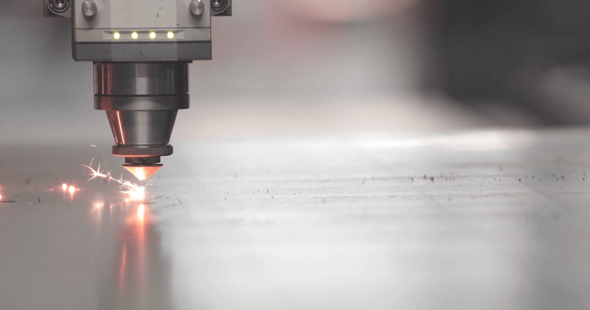
To precisely cut a wire part, the laser light needs to be concentrated to the exact point that it is needed. Apart from very large lasers, this is mainly achieved by focusing the light onto the wire with a lens. This is exactly the same way you would burn paper by magnifying the sun’s rays with a magnifying glass. To burn a line, you would need to move the lens relative to the paper.
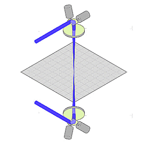
When stripping a wire, it is necessary to cut right around the wire circumference. This is usually achieved by making a cut from opposite sides. For very thick wires it may be necessary to cut right around the circumference by spinning the wire or the laser beam – but for thinner wires (<5 mm / 0.2″ diameter) – it is enough to cut from two sides and have the two cuts join up.
To strip the wire from two sides the light is strongly absorbed by the outer layer before reflecting from the substrate. This forms a stable self-limiting process with no damage to the substrate.
There are 3 main methods for moving the focused laser spot relative to the substrate:
- Fix the laser spot and move the part
- Move the lens relative to the wire (moving optics)
- Change the angle of the laser through the lens (galvanometer scanner)
The first method is simple, but has the major drawback that the product must move. For larger and longer cables this is clearly not possible. Even for smaller cables it can be undesirable as any movement of the part can result in reduced quality stripping.
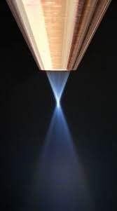
Laser nozzle focuses the laser light onto the wire
Two axes machine with two laser nozzles
The second method is perhaps the most common method used when making a laser wire stripper. The laser beam is directed by a series of mirrors to a laser “nozzle”. The nozzle contains a lens which focuses the light onto the wire.
The nozzle is moved in one or two axes to cut across with wire, or in some cases, along it (see below). In order to strip from two sides of the wire the laser beam needs to be split to be directed to the 2 nozzles.
This can either be achieved by splitting the light 50:50 wire a partially reflecting mirror, or by having a mirror “shuttle” into and out of the beam, sequentially stripping the wire from one side and then the other.
This method has the advantage that overlap of the two laser beams is relatively stable – although can be difficult to set up for a dual axis machine.
A disadvantage is that the relatively large mass of the stages and optics severely limits the maximum acceleration of the laser spot – which limits maximum speeds.
On the other hand, it is easy to achieve large process areas without compromising the laser spot size.
In the third method, a device called a galvanometer scanner (or “galvo” for short) is used to direct the beam. A galvo is a mirror mounted onto an electromagnetic galvanometer. A current passed through the galvo coil causes a fixed deflection.
The laser mirror can be tilted with high accuracy and high acceleration. This allows the laser spot to be deflected at very high speeds (>100 times the moving optics method).
By using two galvos, the laser spot can be directed in two axes. To ensure the laser light is focused in the same plane, no matter the positions of the mirrors, a special lens shape is used called an “f-theta” lens.
The main reason to use this method is to achieve high laser spot speeds which are needed if the laser spot is to be used to burn an area of insulation (area ablation – see below).
This key advantage is achieved at the expense of the working area (for a given laser spot size) – although careful design can mitigate this somewhat. Note that high speed motion of the laser spot is also important for minimizing heat damage of the part.

